|
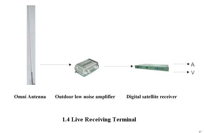
Connection diagram of receiving terminal
Technical Parameters:
◇ Working Frequency 1.0-1.5 GHZ
Frequency is adjustable in a row. It is limited by the receive filter bandwidth and the receiving and
transmission antenna’s bandwidth, and the operating frequency is the center frequency of ± 20M
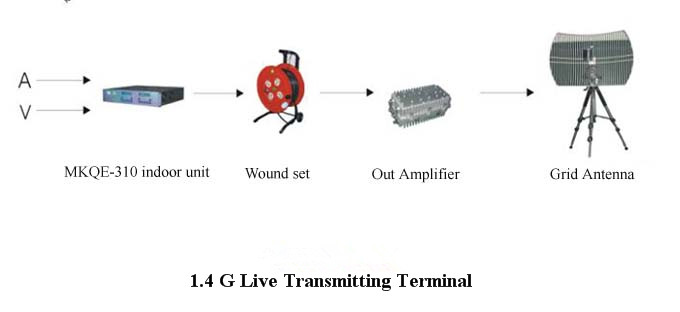
◇ Transmission power 10W
◇ Frequency steady 1×10⁻⁹
◇ Transmission antenna configuration 0.6×0.9mmesh parabolic antenna( provide portable tripod)
◇ Receiving antenna 10 dB Omni-directional antenna(1.8meters’ high)
Route Computing:
PT: 1dB compression point of transmitter power is10W, it is 40dB. When transmit a program, the
bandwidth occupied by about 4.5MHZ with a set of program code rate calculated according to 6M
The actually transmission power is that program based on the share bandwidth back about 4-7 dB.
Now we are transmitting a program, and the getting back value is 5, that is the actual transmission power
for 35dB, about 4W.
F: Frequency=1.5GHz (some frequency points with less disturbance sources are suggested to use)
G: Receiving antenna gain= transmitting antenna configuration is 0.6×0.9m mesh parabolic transmission antenna(Gain is 20dB)+ receiving antenna configuration is 10 dB Omni-directional antenna(Gain is
6 dB)= 30dB
This is the theoretical value of the antenna, 27 dB calculated by taking into.
D: Distance of two stations =20Km
Lo: Space loss=92.4+20lgD+20lgF=92.4+20lg20+20lg1.5=120dB
Ln: Feed tie-in loss≈1dB
B: Receiving level=PT-Lo-Ln+G=35-121-1+27=-58dB
Digital satellite receiver for reception threshold is -78 to -86dB (relevant to rate).
From the above calculation result, the system reserves 20dB level at least. The system has good stability
and reliability when the live point runs within 20Km.
|